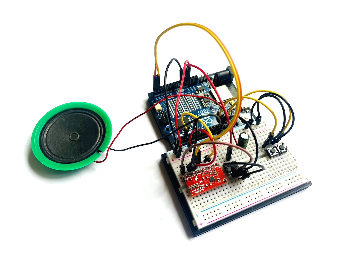
Who hasn’t dreamed of building their own radio? Here at Pollux Labs, you can find an internet radio, but as long as classic FM is still around, there’s no reason not to build a proper receiver for it. In this project, you’ll learn how to create an Arduino FM Radio (also known as an FM Tuner or FM Receiver) with station scanning using just a few inexpensive components.
The heart of the project is an Arduino Uno, which serves as the radio’s brain. It’s paired with a special radio module (Si470x) to handle reception and an LM386 amplifier to push the sound to a speaker.
This project is perfect for beginners looking to get their first experience with the Arduino, I²C communication, and simple audio circuits. By the end, you’ll not only have a cool, self-built gadget but also a deeper understanding of how these components work together. Let’s get started!
These are the Components You’ll Need
For this project, you will need the following components:
- Microcontroller: Arduino UNO
- Radio Module: Si4703
- Amplifier: LM386 Audio Amplifier IC
- Audio Output: 1x small speaker (0.5 Watt at 8 Ohm)
- Controls: 2x Push Buttons
- Wiring: Breadboard and various jumper cables
- Antenna: An approx. 75 cm piece of wire
The Breadboard Setup
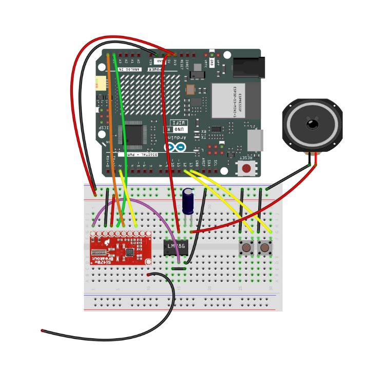
Follow the diagram below to build your Arduino FM Receiver.

Since there’s a lot going on on the breadboard, here are all the connections again in a table.
| Component (From) | Pin on Component | Connection to | Note |
|---|---|---|---|
| Si4703 Radio Module | 3.3V / VCC | 3.3V on Arduino | Important: Do not connect to 5V! |
GND | GND on Arduino | Common Ground | |
SDIO (SDA) | A4 on Arduino | I²C Data Line | |
SCLK (SCL) | A5 on Arduino | I²C Clock Line | |
RST | D2 on Arduino | Reset Line | |
LOUT (Left Out) | Input / + on LM386 | Audio signal to the amplifier | |
ANT | approx. 75cm wire | The antenna, hanging freely | |
| LM386 Amplifier | VS | 5V on Arduino | Power for the amplifier |
GND | GND on Arduino | Common Ground | |
+INPUT | LOUT from Radio | The audio signal goes in here | |
-INPUT | GND | Serves as a reference for +INPUT | |
VOUT | To the speaker with a 100uF capacitor | Amplified audio output | |
| Button 1 | One Pin | D13 on Arduino | Seek Up |
| Other Pin | GND on Arduino | ||
| Button 2 | One Pin | D12 on Arduino | Seek Down |
| Other Pin | GND on Arduino |
How the Radio Works
No radio reception without an antenna, of course. For this, a long, insulated cable (approx. 75 – 100cm) from your workshop will do. You can solder the antenna directly to the radio module or plug it into your breadboard.
The two buttons start the station search: the right one searches upwards for frequencies with reception, and the left button searches downwards.
___STEADY_PAYWALL___
A few words about the speaker: You don’t connect it directly to the output of the LM386, but with a 100uF electrolytic capacitor in between. The capacitor acts as a filter: it blocks DC voltage and only lets the audio signal pass through to the speaker. It’s also called a coupling capacitor. When installing the capacitor, be sure to mind the polarity – the positive side connects to the LM386, and the negative side (marked with a stripe) connects before the speaker terminal.
A Closer Look: The LM386 Audio Amplifier
The audio signal coming directly from the radio module is far too weak to drive a speaker. This is where the LM386 comes in. It’s a classic and very robust audio amplifier chip, perfect for hobby projects. Its job is to take the quiet signal from the radio’s LOUT pin and amplify it so we can hear it clearly.
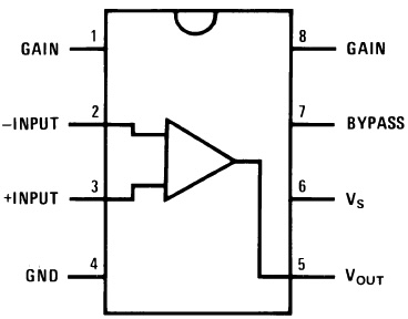
Since the chip itself has no labels, a pinout diagram is essential to identify the connections. Look for the notch on one of the short sides of the chip – this helps you identify the left and right sides of the LM386.

The most important connections for this project:
- Pin 6 (Vs) & Pin 4 (GND): This is where the amplifier gets its power (5V and ground).
- Pin 3 (+INPUT): We connect our audio signal from the radio to this “non-inverting” input.
- Pin 2 (-INPUT): The “inverting” input serves as a reference and is simply connected to ground (GND).
- Pin 5 (Vout): The amplified signal for the speaker comes out here.
We don’t need the other pins (Gain, Bypass) for this simple circuit, but they could be used for higher volume or better noise reduction.
One more thing: The radio module is also available with a headphone jack. With this version, you can skip the LM386 amplifier and even the antenna. Both the sound and reception will come through the headphones and their cable.
The Right Library for the Si4703 Radio Module
To allow your Arduino to talk to the radio module, it needs a suitable library. You can find this in your Arduino IDE’s Library Manager. Simply search for SI470x and install the latest version of the PU2CLR SI470X library. The X here stands for the different versions of the module – besides the 4703, there are also the 4701 and 4702 models.
The Sketch for the Arduino FM Radio
Now for the software for your Arduino FM Tuner. Copy the following sketch and upload it to your Arduino:
/*
  FM Radio with Arduino Uno, Si470x, and LM386
*/

#include <Arduino.h>
#include <Wire.h>      // For I2C communication
#include <SI470X.h>    // The library for the radio module

// Pin definitions
const int RESET_PIN = 2;       // Pin for resetting the radio module
const int SEEK_UP_PIN = 13;    // Button for seeking stations upward
const int SEEK_DOWN_PIN = 12;  // Button for seeking stations downward

// Create a radio object
SI470X radio;

// --- Function to print the current station information ---
void printRadioStatus() {
  // Get current data from the radio chip
  float currentFrequency = radio.getFrequency() / 100.0; // Convert frequency from kHz to MHz
  int currentRSSI = radio.getRssi();

  // --- OUTPUT IN SERIAL MONITOR ---
  Serial.println("--------------------");
  Serial.print("Current Station: ");
  Serial.print(currentFrequency, 2); // Show two decimal places
  Serial.println(" MHz");
  Serial.print("Signal Strength: ");
  Serial.print(currentRSSI);
  Serial.println(" dBuV");
  Serial.println("--------------------");
}

void setup() {
  // Start serial communication for output on the computer
  Serial.begin(9600);
  Serial.println("\n\nStarting Arduino FM Radio...");

  // Configure the button pins as inputs with internal pull-up resistors.
  pinMode(SEEK_UP_PIN, INPUT_PULLUP);
  pinMode(SEEK_DOWN_PIN, INPUT_PULLUP);

  // Initialize I2C communication and the radio module
  Wire.begin();
  radio.setup(RESET_PIN, A4); // A4 is the SDA pin on the Arduino Uno
  Serial.println("Si470x Radio initialized.");

  // Set a threshold for the station seek function.
  radio.setSeekThreshold(45);
  Serial.println("Seek threshold set to 45 dBuV.");

  // Set a medium volume level (0-15)
  radio.setVolume(5);
  Serial.println("Volume set to 5.");

  // Automatically seek the first available station after startup
  Serial.println("Seeking first station...");
  radio.seek(0, 1); // Mode 0 = wrap around at band end, Direction 1 = up

  // Print the status of the first station
  printRadioStatus();

  Serial.println("Setup complete. Radio is ready.");
}

void loop() {
  // Check if the "Seek Up" button was pressed
  if (digitalRead(SEEK_UP_PIN) == LOW) {
    Serial.println("'Seek Up' button pressed -> Seeking next station...");
    radio.seek(0, 1);
    delay(200); // Debounce the button
    printRadioStatus();
  }

  // Check if the "Seek Down" button was pressed
  if (digitalRead(SEEK_DOWN_PIN) == LOW) {
    Serial.println("'Seek Down' button pressed -> Seeking previous station...");
    radio.seek(0, 0); // Direction 0 = down
    delay(200);
    printRadioStatus();
  }

  // Short pause to prevent overloading the loop
  delay(50);
}
How the Sketch Works
Even though the code might look complex at first glance, it can be broken down into three logical blocks. Let’s take a closer look at the most important commands.
The setup() Block: The Preparation
This part runs only once when the Arduino starts.
Serial.begin(9600);: Starts communication with the computer so we can see messages in the Serial Monitor.pinMode(..., INPUT_PULLUP);: Configures the pins for the station search buttons. The Arduino activates an internal resistor that ensures the pin has a clear HIGH signal as long as the button is not pressed. This makes the circuit more stable.radio.setup(RESET_PIN, A4);: Wakes up the radio module and establishes I²C communication.radio.setSeekThreshold(45);: Sets the “quality filter” for the search. Only stations with a signal strength of at least 45 dBuV will be considered. If you are receiving too few stations, choose a lower value.radio.setVolume(5);: Sets the base volume. You can adjust this as needed.radio.seek(0, 1);: Starts the first automatic scan to find a station right after turning it on.
The loop() Block: The Endless Cycle
This code runs over and over as long as the radio is on.
- The Arduino constantly checks if the station search buttons have been pressed.
- If one of the buttons is pressed, the search command is sent to the radio.
The printRadioStatus() Function
- Every time it’s called, it gets the current frequency (
radio.getFrequency()) and signal strength (radio.getRssi()) from the module and prints them in a nicely formatted way to the Serial Monitor.
How to Extend the Arduino Radio
The current setup of your Arduino FM Radio might just be the beginning: you could connect an OLED display to show the current frequency. A very useful extension is a potentiometer to control the volume. And finally, the Si4703 radio module also supports RDS (Radio Data System) – this allows you to receive additional information, provided the stations broadcast it on their frequency.

